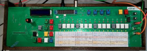
SSequencer BETA Release
OK... here's the info you need to build your own SSequencer. This page is a work in progress so if you need help please email me at 
First off if you want to learn more about the sequencer watch the videos here -> HearMe Studio YouTube Channel
Before you get PCBs made, email me. I may have singles I'm planning to sell at cost - I currently have 4.
Here is the Gerber File zip for the PCB (version beta 1 - 2/12/2023 - 99% sure final version)
You can just submit this to jlcpcb.com or where ever you get your PCBs.
Here is the schematic. (version beta 1 - 2/12/2023 - 99% sure final version)
Here is the BOM (version beta 1 - 2/12/2023 - 99% sure final version)
Here is an assembly video: TODO and assembly notes
Here is the Arduino code (version beta 1 - 4/20/2023 - beta with bugs ). Copy this into your Arduino folder and upload to the Due.
| Release | Significant Changes |
|---|---|
| 4/20/2023 | pressing and holding the solo or mute ctrl button before a queued bank switches will make any solo/mute changes affect the previous bank. This allows you to tweak the solo/mute on the previous bank while the current bank is playing so when you go back it is ready; Shift+8 displays playing notes for the selected track on a mini keyboard in the display. Helps hint what notes are playing for a part. Added Midi/PortB Drum Trigger setting (knob+9 shortcut). When enabled you can map (Shift+MIDI+note) a drum pad trigger IN via midi note (I'm using a beatstep) to one of the drum tracks. This only works with Midi In Port B. Improved backup/restore. On power up/reset all backups except the last one are deleted, so you are left with a clear slate. Backup points are made on STOP if something has changed. Doing a restore (yellow+4) will display the most resent backup. You can then go back in time by minutes to find the best restore point. |
| 2/20/2023 | SHIFT+KnobBtn is no longer default back/cancel; SHIFT+BlackBtn is now default back/exit/cancel; Velocity/Accent settings no longer have "quick select" (red led bar & white buttons). Turn knob to change value by 10, use SHIFT+turn knob to change setting by 1 (this allows you to quick change drum track while editing velocity values); Red LED setting now available on settings shortcuts; robot octave buttons moved left (see new legend);bug fixes |
| 2/12/2023 | Initial beta release; used in walk-thru video |
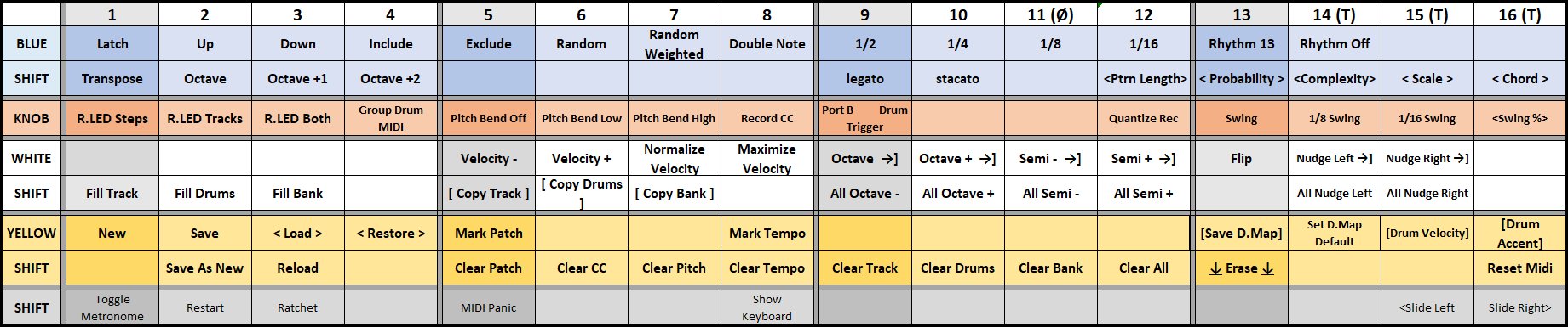
Here is the Cheat Sheet instructions (version beta 1 - 4/20/2023 - beta - will change)
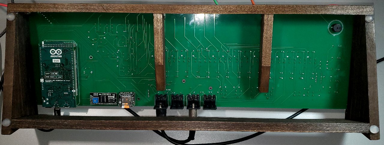
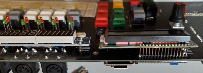
Here is a picture of the backside:
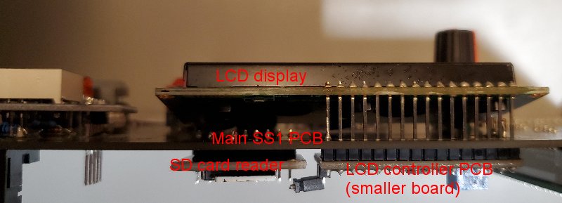
The only tricky part of the build is installing the displays. Do this last! as there are parts underneath the displays that need to be installed first. The LCD display has two parts that sandwich the main PCB. Therefore the display needs the longer header pins to join the two parts. Solder the normal 4 pin header to the LCD controller first (the smaller LCD PCB), and also solder the long 16 pin header to the controller board. Then pass through the main SS1 PCB. There is no electrical connection between the LCD 16 pin header and the main SS1 PCB, it just pass through the PCB, so you don't need to solder all of them. Here I just soldered the two end pins to provide stability. You do need to solder all 4 of the 4 pin header to the main SS1 PCB.
Here are some photos:
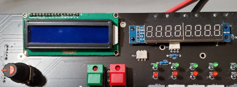

You can also use the longer header pins on the 7-segment display PCB.
Note the SD card reader needs to be installed first. Also note that the SD card reader faces down toward the floor when the SS1 is in normal orientation on a table. The SD card should face out the back along with the midi and power connectors.
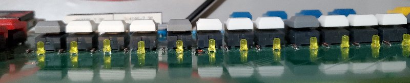
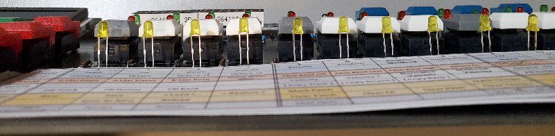
When installing the LEDs you can decide to install them flush to the PCB or raised if you are going to build a front panel. He is an example of both:
The MIDI ports when looking down on the sequencer from normal user position are MIDI IN PORT 1, MIDI IN PORT 2, MIDI OUT PORT 1, MIDI OUT PORT 2 (MIDI IN 1 is closer to the LCD display).